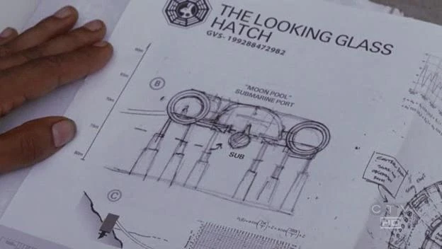
Panels B and C of the Looking Glass schematic ("Greatest Hits")

The Looking Glass schematic is a diagram of the underwater station, The Looking Glass, first seen in "Greatest Hits". Sayid produced the schematic following a discussion with Juliet in which she noted that the existence of an underwater station that was being used to jam communications. He presumably gained possession of the binder containing the schematic when he took documents from the Flame station. ("Enter 77")
Panel A of the schematic is a plan view, showing the station as a circular structure with a control room and a central moon pool. A submarine is shown docked with the station. There are several notations in this panel:
- Control Room "Sonar and Observation Room"
- Int=Sonar & Observation Station with Submarine Dock
- Submarine docks to structure from below
The cable is shown in two different places on the schematic, in Panels A and C. Panel A shows the cable with the label "anchor to land". Panel C contains a side elevation of the cable going into a square mounting structure near the shore.
Panel B of the schematic is a side elevation of the station, which shows that the sea bed is 80m below sea level, and the station is approximately 7m tall, standing on 10m supports. From this scale, the station appears to be about 20m wide.
There are mathematical formulas and graphs on the schematic that seem to be associated with prediction of the water level, consistent with the operation of an underwater submarine dock in a tidal zone. The formulas are a simple tidal constituent equation (shown below) and a complex tidal constituent equation (see Trivia section).


Tidal constituent equation and tidal chart ("Greatest Hits") (promotional still)
The graph above Panel A shows an oscillating signal that may be a plot of water level versus time, given the proximity of the graph to the complex tidal constituent equation. The graph to the right of Panel C appears to be a tide chart for the month of June.
Differences between the Looking Glass station and the schematic
There are several inconsistencies between the station as discovered by Charlie and the schematic.
- The cable as represented on the diagrams does not match the current (2004) configuration of the cable on the island.
- The depth of the station on the schematic (~70 m) does not appear to agree with the actual station's depth, as Desmond and Charlie were able to see it from the surface, and could swim ('free dive') down to it; without weeks of training, a good swimmer could not free dive more than about 10 m; deeper than 30 m, they would risk lung collapse from ambient pressure not nitrogen narcosis. Nitrogen narcosis occurs when breathing compressed air at depth. Snorkelers are to stay above 66 feet or about 22 meters because of the pressure of 3 atmospheres. Pressure in atmospheres absolute includes the weight of the water, which at about 33 feet is 1 atmosphere (14.7 pounds per square inch), plus the atmospheric pressure at the surface, which is 1 atmosphere. So a diver at a depth of 33 feet is exposed to a total pressure of 2 atmospheres absolute, or twice the atmospheric pressure at the surface. With each additional 33 feet of depth, the pressure increases by 1 atmosphere. You divide into the lung volume of 10pts. At/about 2.5 pts (1/4 volume)the lungs start to collapse and the alveoli rupture to keep the lung from fully collapsing. You run the risk of "Pulmonary edema of immersion" The above physics is explained with Boyle's law.
- The Looking Glass logo on the exterior of the station is different from that shown in the schematics.
Trivia
- The document uses the word "hatch"
- This has been confirmed as a prop error by Gregg Nations, the schematic should have read "The Looking Glass Station".
- This is the first glimpse at the Looking Glass logo.
- A "moon pool", as mentioned on the schematic, is a term for a pressurized opening to water on nautical research ships and stations.
- The source document for some of the information used in this prop is almost certainly Tidal Hydrology, Hydraulics and Scour at Bridges, US Department of Transportation, Federal Highway Administration, Hydraulic Engineering Circular No. 25, Publication No. FHWA-NHI -05-077, December 2004. [1] The two equations on the schematic are identical to equations 2.1 and 2.2 in the US DOT document. Also, the image in the lower right hand corner of the schematic is identical to one on page 34 of the US DOT document captioned Figure 2.8. Tide levels along the James River, Virginia.
Unanswered questions
| Unanswered questions |
|---|
|
- For fan theories about these unanswered questions, see: Looking Glass schematic/Theories
- Why does the schematic appear inconsistent with the actual appearance of the station?
